TM 9-2540-207-14&P
5.2.5
Electronic Programmed Controller & Vent Fan Driver Boards (continued)
Installation
1.
If Vent Fan Driver Board and Electronic Programmed Controller Board have been taken apart:
i.
Apply Loctite 242 (blue) to the threads of the screws before using a #1 cross-tip screwdriver, and
fastening the Electronic Vent Fan Driver Board to the Electronic Programmed Controller with two (2)
screws.
2.
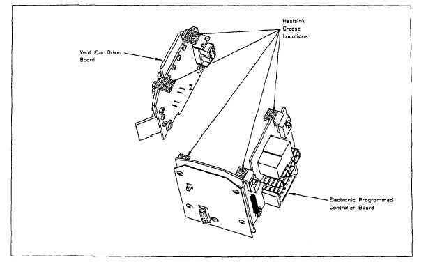
Apply Dow Corning 340 Heat Sink Compound to each of the mounting bracket surfaces of the printed circuit
board assembly.
Note: The surfaces to be coated are metal bracket surfaces that will be in direct
contact with the Vent Fan Housing when the printed circuit assembly is installed.
Figure 5-2.13. Detail, Circuit Board Brackets Requiring Heat-sink Compound
3.
Install the Printed Circuit Board Assembly into the Vent Fan Assembly, aligning the hole in the open bracket with
the hole in the Motor Housing. Apply Loctite 242 (blue) to the screws and using a #1 cross-tip screwdriver
secure using the five (5) flathead screws.
Tip: Place the five (5) flat-head screws in the printed circuit board mounting holes
first, then align and lower the assembly into place. Start EACH screw before
securing any of them.
4.
Connect the Vent Fan Motor Connector to the Vent Fan Driver Board, ensuring the connector locking tabs are
properly engaged.
5.
Install Vent Fan Assembly to Heater (ref. 5.2.1)
5-23