TM 9-4520-257-12&P 0002 00
0002 00-3
Accessories. The shaker (17) and poker (18) are included to aid in tending the burning fuel inside the
H-45. The shaker (17) can be used to access the shaker catch through the grate heater door (20) and
shake the grate in order to move the ashes into the lower portion of the heater. The poker (18) is used to
move live fuel around in the top heater shell. The shovel (19) is used to remove ashes from the lower
section of the heater.
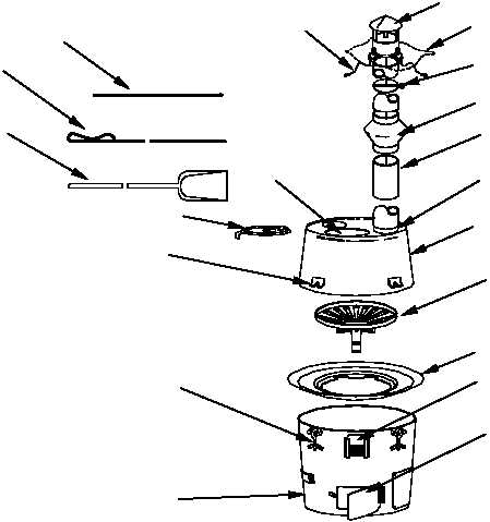
Major Components Of The H-45 Type II (Liquid Fuel) Heater
Heater assembly. The Type II (Liquid Fuel) Heater assembly consists of a heater body base (1) and a
top heater shell (2). The heater body base (1) serves as a base for the assembled heater. It houses the
burner shell assembly (3) during operation. Two heater body base doors (4) are cut into the heater body
base (1) at opposite positions to allow air for combustion. A support (5) to hold the fuel flow control valve
bracket (6) is welded adjacent to the front heater body base door. Three evenly spaced bolt and wing nut
assemblies (7) are welded to the heater body base (1). Three evenly spaced brackets (8) are welded to
the top heater shell (2). The three bolt and wing nut assemblies (7) secure the top heater shell (2) to the
heater body base (1) when the bolts are slid into the brackets (8) and the wing nuts are tightened. During
the operation of the H-45 Type II (Liquid Fuel) Heater, the top heater shell (2) is placed onto the heater
body base (1) and secured. The top heater shell (2) has one internally flanged, 9-inch (22.86-centimeter
(cm)) circular cutout (9) to accommodate the lid (10), and one externally flanged 4-inch (10.16-cm)
cutout (11) that serves as mounting for the stack pipe sections (12).
1
2
3
4
6
5
7
8
9
10
11
12
13
14
15
16
17
18
19
20
Major Components Of The H-45 Type I (Solid Fuel)