TM 9-4520-258-14
4-24. CONTROL BOX ASSEMBLY - continued.
c.Assembly - continued (Refer to Figure 4-31)
(8)
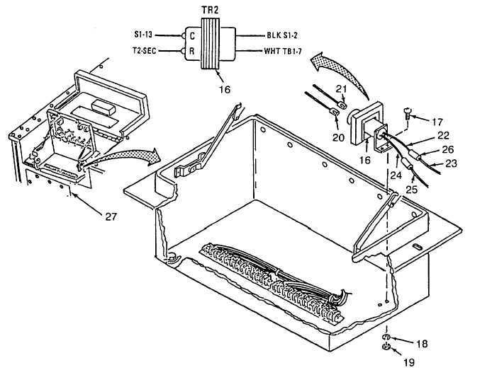
Install transformer (16), two screws (17), two lockwashers (18) and two nuts (19).
(9)
Connect wire TR2-R/TB3-3 (20) and TR2-C1S1-13 (21).
(10)
Connect the black wire (22) to wire S1-12 (23) and the white wire (24) to wire TB1-7 (25) with two
terminal splices (26).
(11) Close right side rear door (27).
Figure 4-31. Control Box Assembly Terminal Boards/Transformer (Sheet 3 of 3)
4-104

