TM 9-4520-258-14
4-24. CONTROL BOX ASSEMBLY - continued.
c.
Assembly - continued (Refer to Figure 4-33)
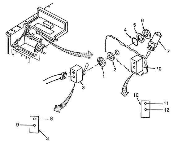
Purge and Flame Reset Switches
NOTE
Both switches are the same.
(15) Install nut (1), locking ring (2), switch (3), preformed packing (4) (Item 39, App H), lockwasher (5) and
nut (6).
(16)
Install extention (7).
(17)
Purge Switch (3) - connect wire S4-1 (8) and wire S4-2 (9).
(18)
Flame Reset Switch (10) - connect wire S7-1 (11) and wire S7-2 (12).
Figure 4-33. Control Box Assembly, Purge and Flame Reset Switches
4-106