TM 9-4520-258-14
5-3. CONTROL BOX ASSEMBLY - continued.
b.
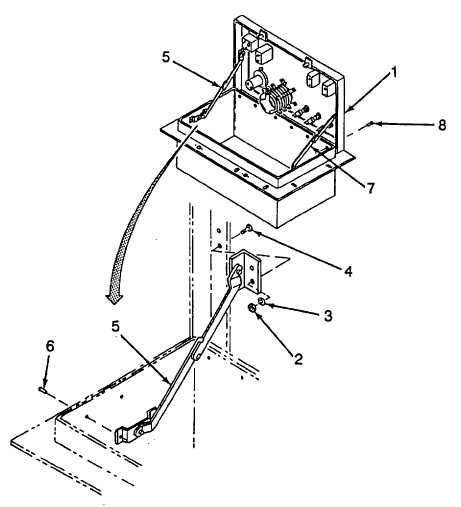
Disassembly (Refer to Figure 5-3)
(1)
Open control box cover (1).
(2)
Remove two self-locking nuts (2), two flatwashers (3), two screws (4) and the top end of
right support (5).
(3)
Drill out two rivets (6) and remove the bottom end of right support (5).
(4)
Repeat steps (2) and (3) to remove the left support (7).
(5)
Drill out six rivets (8) and remove cover (1).
Figure 5-3. Control Box Disassembly (Sheet 1 of 2)
5-6

