TM 9-4520-258-14
5-3. CONTROL BOX ASSEMBLY - continued.
d.
Assembly - continued (Refer to Figure 5-4)
(6)
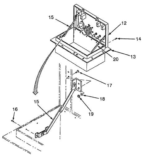
Position cover (12) on control box (13) and secure with six rivets (14).
(7)
Position bottom end of left handed support (15) and secure with two rivets (16).
(8)
Install top end of left hand support (15), two screws (17), two flat washers (18) and two locknuts (19).
(9)
Repeat steps (7) and (8) for right hand support (20).
Figure 5-4. Control Box Assembly (Sheet 2 of 2)
5-9