TM 9-4520-258-14
5-5.
BURNER ASSEMBLY - continued.
c.
Assembly - continued (Refer to Figure 5-9)
(4)
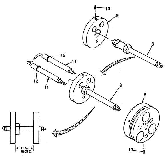
Install fuel tube (8) into baffle (9) until baffle contacts hex nut on fuel tube. Secure fuel tube (8) and
baffle (9) with setscrew (10).
(5)
To help keep baffle and block aligned, insert the two electrodes (11) and preformed packing (12).
Remove after completing next steps.
(6)
Install fuel tube (8) through the center hole in the front of block (5). The distance between the front of
block (5) and the back of baffle (9) is 1-1/4 in. Secure fuel tube in block by tightening setscrew (13).
Figure 5-9. Burner Assembly (Sheet 2 of 5)
5-19

