TM 9-4520-258-14
5-5.
BURNER ASSEMBLY- continued.
c.
Assembly - continued (Refer to Figure 5-9)
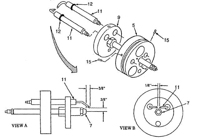
(12) Insert the two electrodes (11) into baffle (9) and block (5), making sure preformed packing (12) is
inserted into baffle.
(13)
Install two setscrews (15) but do not tighten at this time.
(14)
Position the electrode (11) tips 3/8 inch in front of nozzle (7) and 318 inch above the nozzle discharge
port (View A).
CAUTION
Electrodes may be damaged during bending of electrode. Care must be taken when bending the
electrode tips.
(15) Tighten two setscrews (15) snuggly, do not over tighten.
(16) Carefully bend the gap between the two electrodes (11) to 1/8 inch (View B).
(17)
Recheck electrodes position. Repeat steps 13 thru 15 if necessary.
(18)
Check position of two preformed packings (12). They should be approximately centered in the baffle
(9).
Figure 5-9. Burner Assembly (Sheet 4 of 5)
5-21