
TM 9-4520-271-14
0051 00
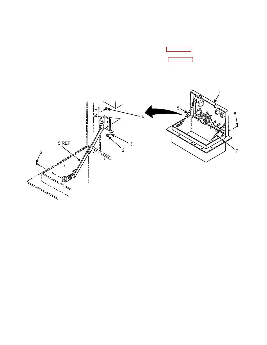
ASSEMBLY
Continued
5.
Position control box assembly panel (1) and secure with six rivets (8) (item 6, WP 0062 00).
6.
Position bottom end of right support (5) and secure with two rivets (6) (item 8, WP 0062 00).
7.
Install top end of right support (5) with two screws (4), washers (3), and locknuts (2).
8.
Repeat steps 6 and 7 and install left support (7).
0051 00-5
