
TM 9-4520-272-14&P
0050 00
ADJUST continued
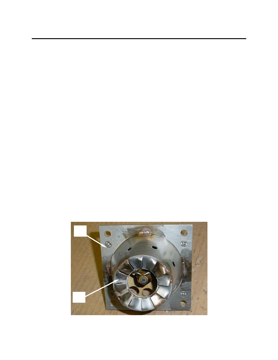
1. Insert the supplied electrode gap adjusting tool (27) so that it falls between the tips (28 and 29) of the
two electrodes and the angled shoulders (30) of the tool are in contact with the inner ring (31) of the
burner cone with swirlers (25). Verify that the tip of the nozzle (32) is in contact with the end (33) of
the electrode adjusting tool without raising the adjusting tool off the inner ring (31) of the burner cone
with swirlers (25). Verify also that the center of the tip of the nozzle (32) is aligned with the center line
(34) of the adjusting tool (27). This line is labeled "C/L Nozzle" (C/L = Center Line). If the nozzle is not
in the correct position, loosen the three nozzle adjustment screws (39, 40, and 41) and move the
nozzle so that it is aligned with the centerline (34). Tighten the nozzle adjustment screws just enough
to hold the nozzle in position.
2. Rotate the adjusting tool (27) 90 degrees and position the angled shoulders (30) of the tool so that
they are in contact with the inner ring (31) of the burner cone with swirlers (25). Verify again that the
center of the nozzle is aligned with the center line (34) of the adjusting tool. If the nozzle is not in the
correct position, loosen the three nozzle adjustment screws (39, 40, and 41) once again and move
the nozzle (32) so that it is aligned with the centerline (34). Alternate the position of the adjusting tool
back and forth 90 degrees to ensure that the nozzle is centered along two axes. Once alignment is
verified, tighten the nozzle adjustment screws (39, 40, and 41) securely.
3. With the adjusting tool (27) positioned so that is in contact with both electrode tips (28 and 29), verify
that the gap between the electrode tips is correct by aligning with the two indicator lines (35 and 36)
on the adjusting tool (27). Verify also that the electrode tips are the correct distance from the end of
the nozzle by verifying that the tips of the electrodes are aligned with the horizontal lines (37 and 38)
of the crosshairs.
4. If the electrodes are out of alignment, loosen the allen set screw (42) for the right hand electrode (43)
and position the electrode so that it is aligned with the indicator line (36) to the right of center and at
the same level as the horizontal line (38) of the crosshair. Tighten the allen set screw (42).
5. Check the alignment of the left hand electrode tip (28). If not aligned with the indicator line (35) to the
left of center, loosen the allen set screw (44) for the left hand electrode (45) and set the electrode gap
so that it is aligned with the indicator line (35) to the left of center and at the same level as the
horizontal line (37) of the crosshair. Tighten the allen set screw (44).
23
25
0050 00-6
