TM 9-4520-272-14&P
0050 00
INSTALL
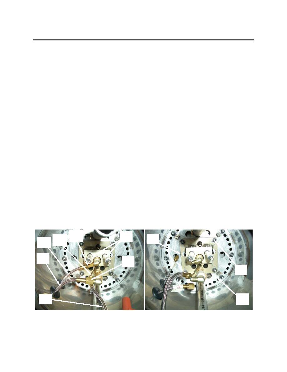
1. Position burner nozzle and electrode assembly (23) in burner cone assembly (24) and install the four
nuts, lock washers, and flat washers (22) that secure the burner nozzle and electrode assembly (23)
to the burner cone assembly (24).
2. Install the two fuel lines (16 and 17) and the pressure gauge line (18). Tighten fittings (19, 20, and
21) securely.
3. Connect the two high voltage ignition cables (14) to the burner electrode connectors (15).
4. Position the upper burner cover (8) with ignition pack (12) and pressure gauge (13) attached so that
the burner sight glass fitting (46) passes through the hole in the cover (8) and the threaded studs (9)
pass through the holes in the cover.
5. Install the upper four nuts, lock washers, flat washers (10), and wire harness clamp securing the
upper burner cover (8).
6. Reconnect ignition pack wire harness (11).
7. Slide the combustion air mounting bracket (6) back into position over the four lower threaded studs
(9).
8. Install the four nuts, lock washers, flat washers (7), and wire harness clamp securing the combustion
air mounting bracket (6) to the upper burner cover (8).
9. Tighten the band clamp (4) securing the combustion blower motor (5) to combustion air mounting
bracket (6).
10. Install the sight glass and coupler assembly (3) by grasping coupler with slip joint pliers and turning
clockwise.
11. Install flame sensor assembly (2) and secure with clamp (1).
19
15
20
23
16
17
21
22
24
18
0050 00-9


