
Section VI. TROUBLESHOOTING
the defective component. Do not overlook the
General
importance of questioning the operator to get as
This section contains troubleshooting information
many definite symptoms as possible.
in tabular form to help in locating and correcting
s o m e of the common troubles which may develop in
Troubleshooting
Procedures
the heater. This section cannot cover all of the
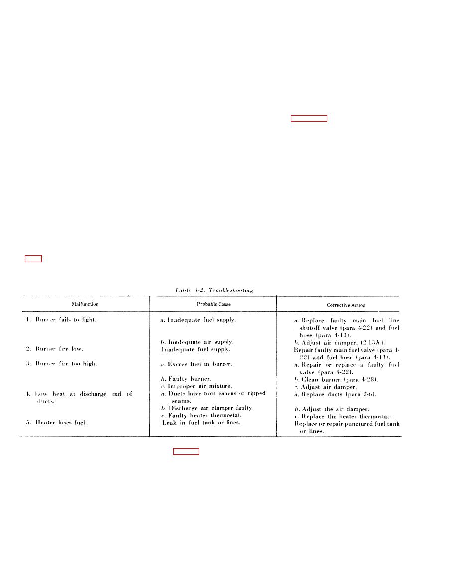
Malfunctions and troubleshooting procedures for
troubles or malfunctions that may occur. If a
t h e engine assembly are shown in TM5-2805-256-
s p e c i f i c m a l f u n c t i o n o r t h e t r o u b l e s h o o t i n g in-
14. Malfunctions and troubleshooting for the
s t r u c t i o n is not covered in these charts, isolate the
heater are listed in table 4-2.
s y s t e m in which the trouble occurs and then locate
Section VII. RADIO INTERFERENCE SUPPRESSION
Radio interference suppression components
are
described in TM5-2805-256-14.
Section VlIl. MAINTENANCE OF THE ENGINE ASSEMBLY
remove the flexible fuel line at the engine fuel
pump.
a.
Removal.
(3) Remove the two screws holding the
(1) Close the main fuel line shutoff valve (fig.
flexible line housing clamp to the blower wheel
housing.
(2)
Unscrew
the
flexible
line
coupling
and
(4) Remove the self-locking nuts (1, fig. 4-1)
( 8 ) Remove the engine and the mounting base
which hold the fan guard (6) to the heater.
b y sliding off the track.
( 9 ) Remove the nuts, bolts, flat washers, and
(5) Remove the bolts which hold the engine
m o u n t i n g base
to
the
left
and
right
engine
lockwashers securing the engine to the engine
mounting brackets.
mounting base, and remove the engine from the
( 6 ) Remove the nuts which are located on the
base.
blower wheel housing duct.
b. Inspection. Check the engine assembly for
(7) Loosen the fan guard from the studs.
cracks, breaks, distortions, and any other visible
defects. If it is defective, replace it as authorized.
