
TM 5-4520-208-15
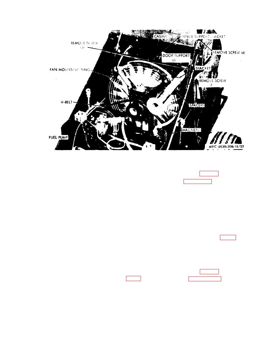
Figure 27. Fan mounting ring, removal points (BT400-40-1).
(4) Press fan hub (17) on bearing. Install
(9) Install V-belt (para 76).
vaneaxial fan (18)
on hub and se-
(10) Refer to paragraph 12 and install pow-
cure with three cap screws (21 ) and
er unit.
lockwashers (20).
(5) Position resilient mount (7) on fan
f. Installation (BT400-40-1).
bearing support (6) and secure with
(1) Perform steps (1) through (6) of
two screws (8). Install three fan
paragraph e. above.
guards (10) and secure with three
(2) Install mounting ring in casing. Line
screws (11 and 27), lockwashers (12
up center hole in casing with center
and 32), two flat washers (28) and
hole in mounting ring.
nuts (31).
(6) Install coupling sleeve (1) in flexible
(3) Install hinge support bracket with at-
robber sleeve bushing (2) and place
tached door supports (fig. 27) and
sleeve bushing in coupling half (30).
secure with three screws and lock-
Install two retainers (5) and secure
washers.
with four screws (3) and lockwashers
(4) Connect door supports to cabinet and
(4).
secure with four screws, lockwashers,
(7) Install fan ring, with attached parts,
and nuts.
in casing and secure with three screws
(5) Install V-belt (pars 76).
(14) and lockwashers (15).
(8) Install bracket and spacers (fig. 26)
(6) Refer to paragraph 12 and install
using two screws.
power unit.
47
