TM 5-4520-208-15
(7) Install control box (3) to fuel control
b. Removal.
using two screws (4), lockwashers
(1) Remove control box from controls. Re-
(68), and nuts (67); and two screws
fer to paragraph 97 for BT400-40 and
(1) and lockwashers (2).
(8) Refer to paragraph 77 and install the
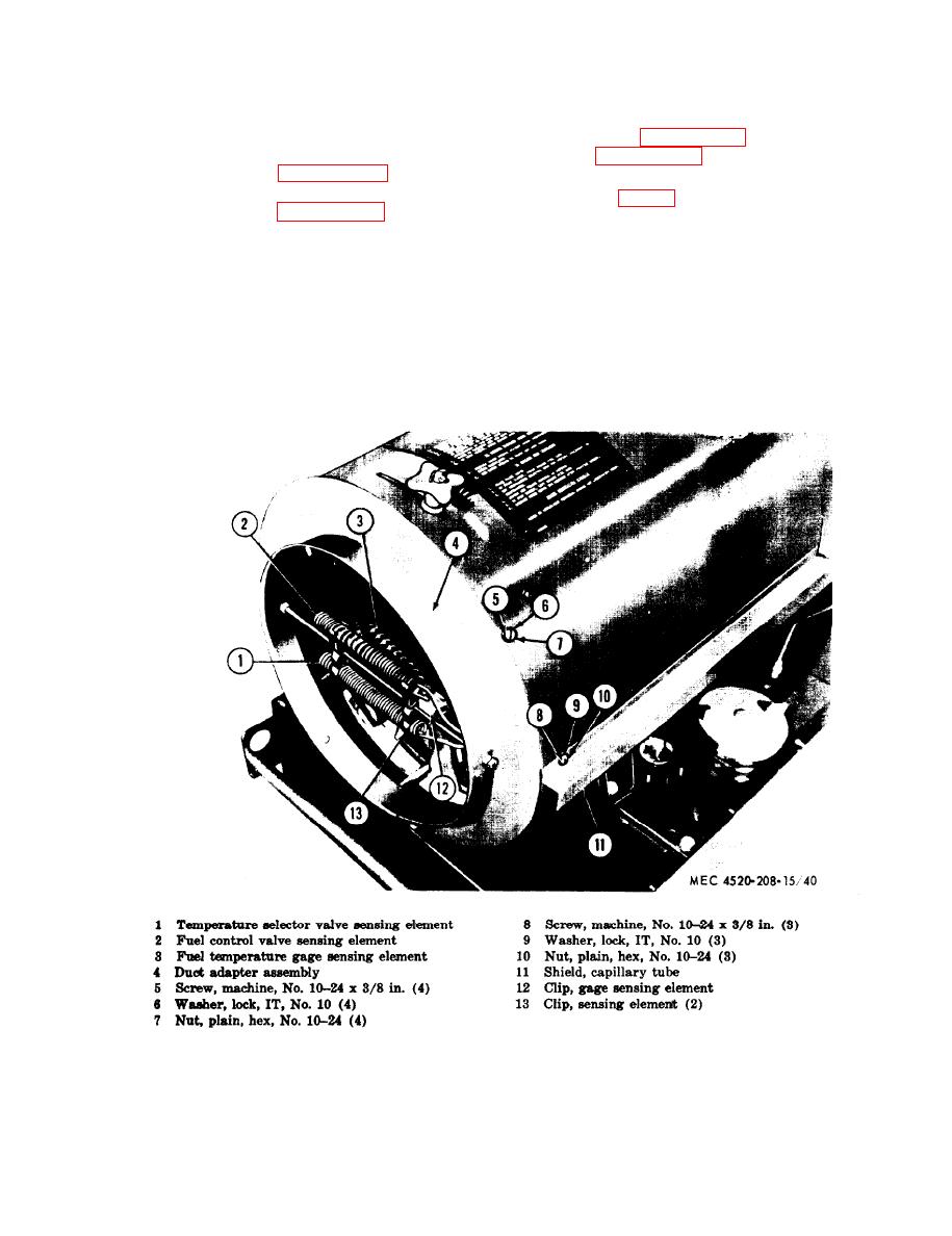
(2) Disengage sensing elements (1, 2, and
fan and mounting ring.
3, fig. 40) from clips (12 and 13).
(9) Refer to paragraph 70 and install cab-
(3) Remove four screws (5), lockwashers
innet and power unit
(6) and nuts (7), and remove duct
adapter assembly (4) from casing.
99. Discharge Temperature Gage
(4) Remove three screws (8), lockwashers
(9), and nuts (10), and remove cap-
a. General. The discharge temperature gage
illary tube shield (11) from casing.
indicates the temperature of the air being dis-
(5) Withdraw temperature gage sensing
charged from the outlet end of the heater in
element through hole in casing.
degrees Fahrenheit. A sensing element, mount-
ed on the discharge end of the heater controls
Note. Steps (6) through (8) below per-
the temperature gage.
tain only to the Model BT400-40 heater.
Figure 40. Air discharge components, removal points.
69


