
4-36 Handle (fig. 4-9)
securing assembly to enclosure base.
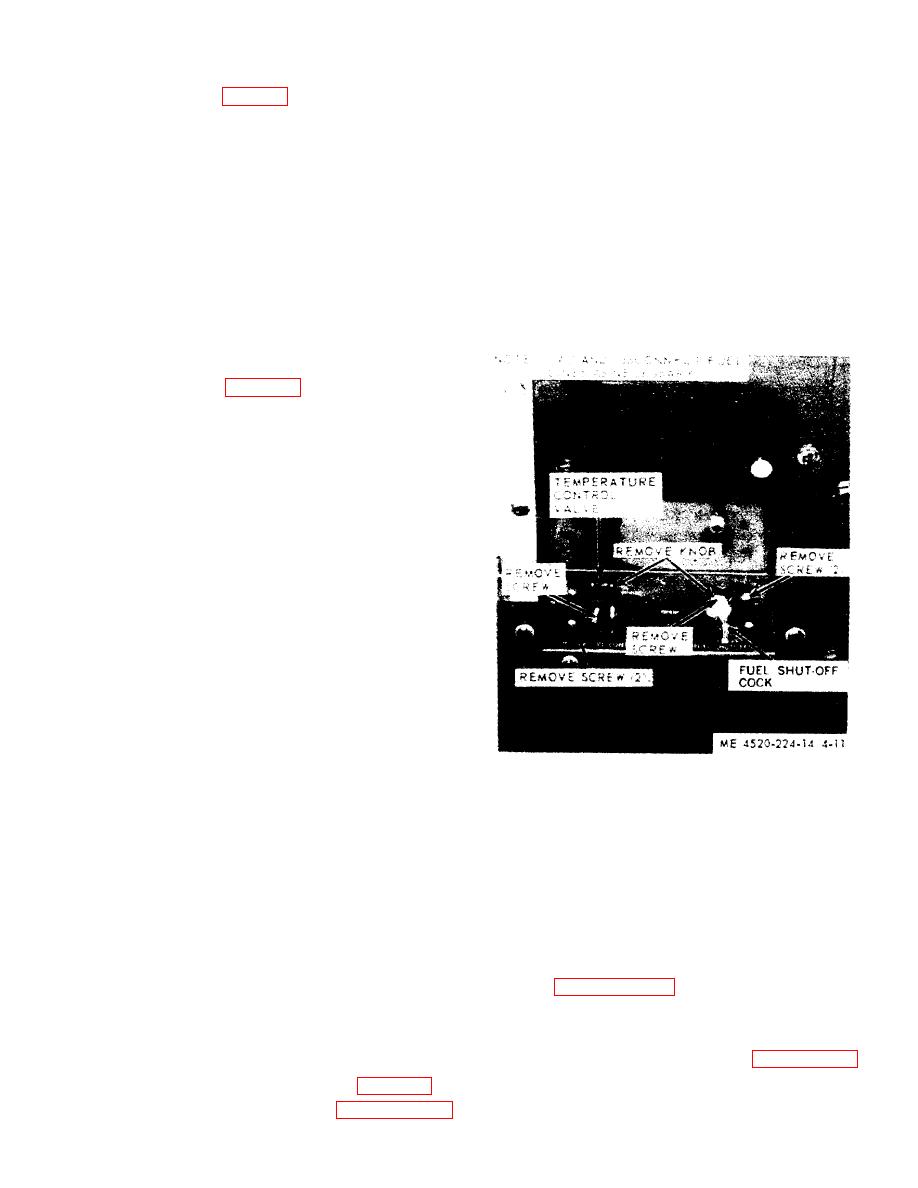
b. Diassembly.
a. Removal.
(1) Remove the knob from the temperature con-
(1) Remove the 4 screws and the lockwashers
trol valve and the handle from the fuel shut-off cock.
from the right heater handle tiedown bracket and
(2) Remove the screws securing the valve bodies
take off the bracket. Remove the left heater handle
to the control box and remove the valves.
tiedown bracket in the same manner.
(3) Remove the screws securing the instruction
(2) Lift the handle from the heater.
plate and remove the instruction plate.
(3) Remove the 4 screws and the lockwashers
c. Inspection. Check for unserviceable components
from the heater handle brace brackets. Remove the 2
and replace.
heater handle braces and the 2 brackets from the
d. Assembly. Reverse the procedures in b. above.
heater.
e. Installation. Reverse the procedures used in a.
b. Inspection. Check the components for dents,
above.
bends, breaks, and cracks. Replace unserviceable
parts.
c. Installation. Reverse the procedure in a. above.
4-37 Damper (fig. 4-10)
a. Removal.
(1) Remove the jamnut and the nut from each of
the two screws on the handle end of the upper dam-
per.
NOTE
As the damper operating shift with handle is pulled out,
a spacer washer and a coil spring will fall from the han-
dle.
(2) Remove the upper damper from the opening.
(3) Remove the lower damper in the same man-
ner.
b. Inspection.
(1) Inspect the dampers for proper operation.
(2) Check the springs for adequate tension and
broken coils.
(3) Straighten any dents.
(4) Replace unserviceable parts.
c. Installation. Reverse the procedure in a. above.
4-38 Tool Pouch
a. Removal.
4-40 General
(1) Unfasten and lift up the tool pouch cover
The fuel is delivered from the fuel tank to the engine
flap.
and heater through flexible metal lines. The fuel is
(2) Remove the 2 capscrews holding the moun-
strained through a strainer before it leaves the fuel
ting strip and tool pouch to the heater, and take off
tank. The fuel tank gage registers the amount of fuel
the mounting strip and the tool pouch.
in the tank. The fuel flow to the heater can be com-
b. Cleaning. Clean the tool pouch and the moun-
pletely shut off with the shut-off cock, or controlled
ting strip with approval cleaning solvent and dry
by the temperature control valve.
them thoroughly.
c. Inspection. Check the tool pouch for holes, tom
4-41 Lines and Fittings
or ripped seams, and damaged snap fasteners. Check
Refer to paragraph 4-18 for maintenance of lines
the mounting strip for bends and breaks. If the tool
and fittings.
pouch and the mounting strip are defective, install
serviceable ones.
d. Installation. Reverse the procedure in a. above.
4-39.
b. Cleanirg. Wash the cock in approved cleaning
solvent and apply air pressure to blow out any
and disconnect the fuel lines and remove 4 capscrews
foreign matter.
