TM 5-4520-253-13
l N S P E C T / R E M O V E / l N S T A L L D A T A P L A T E S ( C O N T)
c.
d.
e.
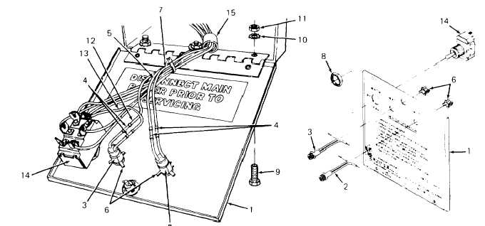
Pull FAULT and HEAT lights (2 and 3) out of mounting holes from front of control box
cover (1 ).
Remove hex nut (8) at front of control box cover (1) and pull HEATER-OFF-FAN switch (14)
out of mounting hole from back of cover.
Remove three screws (9), lock washers (10), and nuts (11). One combination screw/lock
washer/nut retains harness clamp (15). Remove harness clamp and lift off control box
cover ( 1 ).
INSTALLATION:
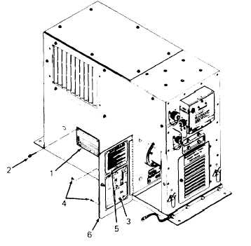
1. Install original identification plate (1)
using four blind rivets (2).
2. Install wiring diagram plate (3) using
four tubular brass rivets (4). Install
sequence of operation plate using
four rivets (4). Install all rivets (4)
with heads on outside of right door
(6).
3-82


