TM 5-4520-253-13
l N S P E C T / R E M O V E / l N S T A L L D A T A P L A T E S ( C O N T )
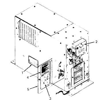
3. Nameplate (2) is printed on heavy-
gauge aluminum. It is the control
box cover. Check for loose rivets
at hinge.
Check for distortion
causing difficult closing or locking.
Replace defective cover.
NOTE
Identification plate (1) is normally never removed. If re-
moved, same identification plate must be installed.
1. Remove identification plate (1) by drilling out four blind rivets from outside heater case. Retain
identification plate for reinstallation.
2. Remove wiring diagram plate (3) and sequence of operation
brass rivets from inside right door (5).
plate (4) by drilling out eight tubular
3. Removal of the
Death or serious injury could occur if precautions are not
taken when maintaining this equipment. Position HEATER-
OFF-FAN switch to OFF, remove power cable plug from
POWER RECEPTACLE, and ground capacitors C1 and C2
at end cover of combustion blower. Always have another
person standing by who is trained in electric shock first aid.
name plate consists of removing the control box cover (1). Proceed as follows:
a.
b.
Disconnect violet wire (5) and yellow wire (7) from leads of FAULT light (2). Disconnect
white wire (12) and orange wire (13) from leads of HEAT light (3). Discard butt connectors
(4). Wire numbers are same as those appearing in table 3-5.
Grasp barrel fasteners (6) with pliers and forcibly remove. Discard fasteners.
3-81


