TM 5-4520-253-13
A D J U S T / l N S P E C T / S E R V I C E / R E M O V E / l N S T A L L D O O R S A N D B O T T O M C O V E R
TOOLS: Tool kit, service, refrigeration unit
NSN 5180-00-596-1474
MATERIALS/PARTS: Antiseize compound (Item 1, Appendix E)
Dry cleaning solvent (Item 13, Appendix E)
GENERAL SAFETY INSTRUCTIONS:
Power off.
Heater cool.
ADJUSTMENT:
Death or serious injury could occur if precautions are not
taken when maintaining this equipment. Position HEATER-
OFF-FAN switch to OFF, remove power cable plug from
POWER RECEPTACLE, and ground capacitors C1 and C2
prior to gaining access to heater compartments. Terminals
of capacitors are accessible at end cover of combustion
blower. Always disconnect power cable before making con-
tinuity tests or before repairing heater. Always have
another person standing by who is trained in electric shock
first aid.
Allow sufficient time for heater to cool to room tempera-
ture before gaining access to heater compartments.
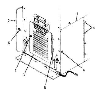
1. Right and left doors (1 and 2) and front
access door (3) are adjusted by the same
procedure as follows:
a. Loosen four screws (4) at right and
left doors (1 and 2) or three screws
(5) at front access door (3). Do not
remove screws.
b. Adjust door vertically until studs (6 and
7) are aligned with their receptacles.
Lock studs by rotating clockwise.
c. Tighten top and bottom screws (4 or
5) to slight tension. Door must be
movable when tapped.
d. Tap door until top and bottom edges
are perfectly horizontal. Tighten all
screws (4 or 5) securely
2. There is no adjustment of the bottom cover.
3-76


