TM 5-4520-253-13
ADJUST/lNSPECT/SERVICE/REMOVE/lNSTALL
DOORS
AND
B O T T O M C O V E R ( C O N T)
REMOVAL:
Death or serious injury could occur if precautions are not
taken when maintaining this equipment. Position HEATER-
OFF-FAN switch to OFF, remove power cable plug from
POWER RECEPTACLE, and ground capacitors C1 and C2
at end cover of combustion blower. Always have another
person standing by who is trained in electric shock first aid.
Remove electrical charge from ventilating air motor capaci-
tor C3 by shorting out contacts using tool having insulated
handle.
Allow sufficient time for heater to cool to room tempera-
ture before gaining access to heater compartments.
NOTE
Open right and left doors and
front access door to allow access
to hardware inside heater case
1.
2.
3.
during removal.
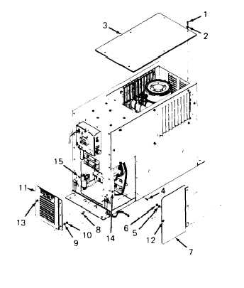
Remove six screws (1) and lock
washers (2} and lift off bottom
cover (3).
Remove four screws (4), lock
washers (5), and nuts (6).
Lift off left door (7). Use
same procedure for removing
right door.
Remove
washers
Lift off
three screws (8), lock
(9), and nuts (10).
front access door (11).
3-78