TM 9-2540-207-14&P
5.5.4
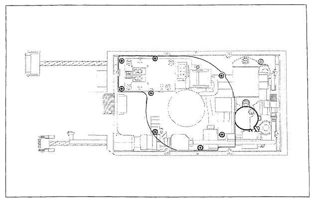
Burner Fan Plate Assembly (continued)
Removal (continued)
Figure 5-5.8. Burner Fan Plate, Screw Locations
!WARNING!
NEVER place Burner Fan Plate Assembly on the Burner Fan impeller. This may
cause warpage of the Impeller.
8.
Using a #2 cross-tip screwdriver, remove the eight (8) mounting screws securing the Burner Fan Plate to the Top
Housing (Note: one screw is shared with the Inductor (L1) clamp). Free the Power Inductor (L1) from its
clamp.
9.
Free the Power Main Capacitor (C2) by loosening the bolt on the side of the Main Capacitor clamp.
10.
Lift the Burner Fan Plate Assembly from the Top Housing while at the same time pushing the MS Power
connector into the Top Housing. Take care not to damage the wires and connectors. Avoid fuel spills.
Note: The Fuel Injector will become loose and can be put aside for re-installation.
Take care NOT to damage the Fuel Injector O-rings.
11.
If REPLACING Burner Fan Plate, remove the Diagnostic Display (ref. 5.5.2) and Fuel Pressure Sensor
(ref. 5.5.1) for re-installation.
5-59