TM 9-4520-258-14
4-26. COMBUSTOR CONTROL RELAY (K1) ASSEMBLY - continued.
e.
Installation (Refer to Figure 4-39)
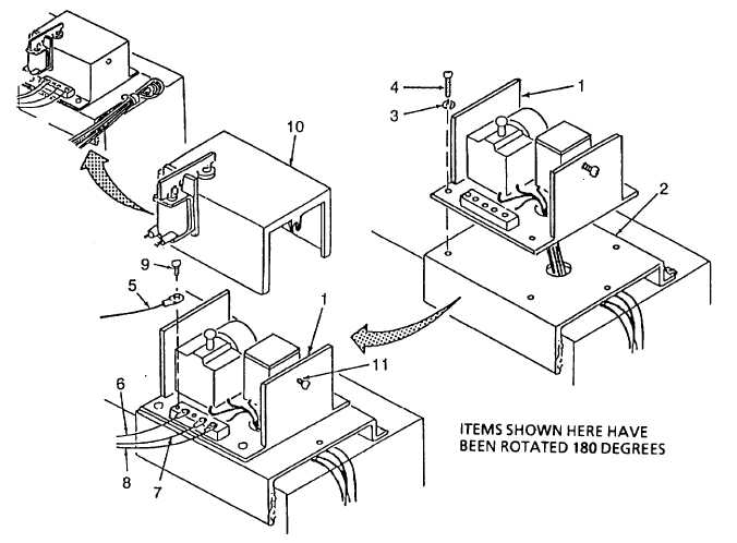
(1) Install combustor control relay (1) while guiding the four colored wires through the hole in the unit
mounting bracket (2) with the wires extending out toward the rear of the unit.
(2)
Install four lockwashers (3) and four screws (4).
(3)
Install wires (5), (6), (7), and (8) with four screws (9) as follows:
(a)
Wire (5) K1-W:TB3-1 connects to position W.
(b)
Wire (6) K1-B:TB3-5 connects to position B.
(c)
Wire (7) K1-F1:TB3-6 connects to position Fl.
(d)
Wire (8) K1-F2:TB3-7 connects to position F2.
(4) Install cover (10) on combustor control relay (1) and tighten screw (11).
Figure 4-39. Combustor Control Relay Installation (Sheet 1 of 2)
4-116