TM 9-4520-258-14
4-26. COMBUSTOR CONTROL RELAY (K1) ASSEMBLY - continued.
e.
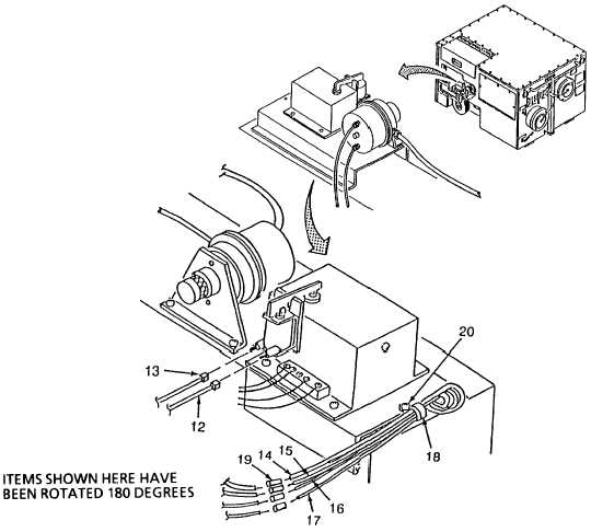
Installation - continued (Refer to Figure 4-39)
(5) Install wires (12) and (13).
(6)
Insert the four colored wires (14), (15), (16), and (17) through clamp (18) and connect the wires using
four crimp splices (19) as follows:
(a)
Black wire (14) connects to wire coming from TB1-11.
(b)
White wire (15) connects to wire coming from TB1-5.
(c)
Orange wire (16) connects to wire coming from TB3-8.
(d)
Red/Yellow wire (17) connects to wire coming form TB3-11.
(7)
Install wire clamp (18) and screw (20).
(8)
Close door (21).
Figure 4-39. Combustor Control Relay Installation (Sheet 2 of 2)
4-117

