TM 9-4520-258-14
4-29.
COMBUSTOR FAN ASSEMBLY - continued.
b.
Disassembly (Refer to Figure 4-49)
(1)
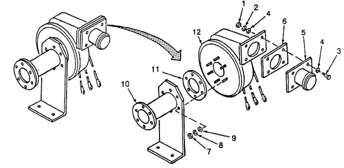
Remove four nuts (1), four lockwashers (2), four screws (3), eight flat washers (4), adapter (5) and gasket
(6). Discard gasket and lockwashers.
(2)
Remove the remaining four nuts (7), four lockwashers (8), four flat washers (9), fan mount bracket (10) and
gasket (11) from fan assembly (12). Discard gasket and lockwashers.
c.
Inspection Inspect parts for wear, cracks or other damage.
d.
Repair Limited to replacement of damaged parts.
e.
Assembly (Refer to Figure 4-49)
(1)
Install gasket (11) (Item 62, App F) on fan assembly (12).
(2)
Position fan assembly (12) on fan mount bracket (10).
NOTE
Leave the 3 o'clock and 9 o'clock positions empty.
(3)
Install four flat washers (9), four lockwashers (8), and four nuts (7), to secure the fan assembly (12) to the
mount bracket (10).
(4)
Position gasket (6) (Item 63, App F) and adapter outlet (5) on fan assembly (12) and secure with eight flat
washers (4), four screws (3), four lockwashers (2), and four nuts (1).
Figure 4-49. Combustor Fan Disassembly/Assembly
4-133


