TM 9-4520-258-14
4-29.
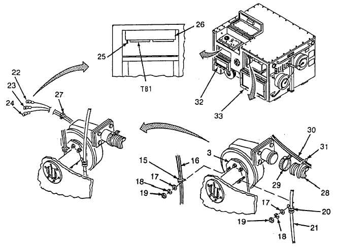
COMBUSTOR FAN ASSEMBLY - continued.
f.
Installation continued (Refer to Figure 4-50)
(8)
Install clamp (15) and wire bundle (16) on fan assembly (3) at the 9 o'clock position, secure with a flat
washer (17), lockwasher (18), and nut (19).
(9)
Install clamp (20) and fuel line (21) on fan assembly at the 3 o'clock position, secure with a flat washer
(17), lockwasher (18) and nut (19).
(10)
Connect the white wire (22) on TB1-5, the black wire (23) on TB -11 and the green wire (24) to the ground
stud (25) on the bottom of the control box (26).
(11)
Route three wires from fan assembly (3) along wire bundle and secure with two wire ties (27).
(12)
Install duct (28) on outlet of fan assembly (3) and secure with clamp (29).
(13)
Route wire bundle (30) along duct (28) and secure with wire ties (31) as required.
(14)
Close and secure doors (32) and (33).
Figure 4-50. Combustor Fan Assembly Installation (Sheet 2 of 2)
4-135