TM 9-4520-271-14
0054 00
DISASSEMBLY
Continued
3.
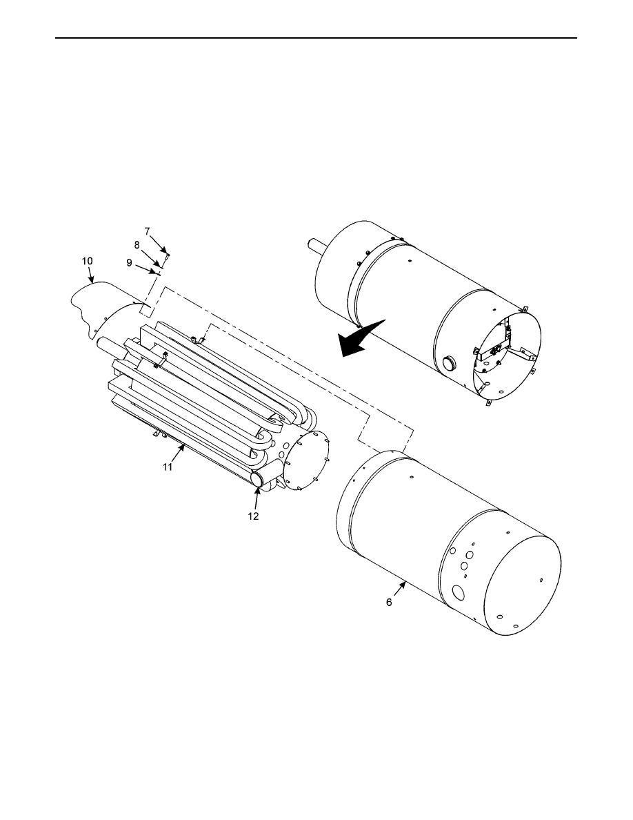
Remove eight screws (7), lockwashers (8), washers (9), and shell extension (10). Discard lockwashers.
NOTE
Heat exchanger assembly shell must be tilted to allow clearance for the heat exchanger assembly air inlet
pipe.
4.
Remove heat exchanger assembly shell (6) from heat exchanger assembly (11) being careful of air inlet pipe (12).
INSPECTION
1.
Inspect all parts for wear, cracks, and corrosion.
2.
Inspect all hardware for stripped or damaged threads.
0054 00-6


