T M 9 - 4 9 3 1 - 3 8 1 - 1 4 & P - 2
FRAME 27
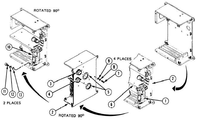
Install Cable Assembly:
1.
Position IDU cable assembly (1) inside housing (2).
2. Using jamnut wrench, put receptacle connectors J1 (3) and J2 (4) into housing (2) and
tighten two jamnuts (5).
3.
Position bracket (6) and screw in and tighten four machine screws (7), new
lockwashers (8), and flat washers (9) with screwdriver.
4. Position electrical bracket (10) and screw in and tighten two machine screws (11),
new lockwashers (12), and flat washers (13) with screwdriver.
Follow-on Maintenance:
I. Install
2. Install
3. Install
4. Install
50 I n s t a l l
6. Install
7. Install
8. Install
electron tube assembly and clamp; refer to task 14.
power supply; refer to task 15.
circuit card assemblies A1 and A2, refer to task 16.
cover; refer to task 17.
eyepiece assembly and adapter; refer to task 13.
IDU assembly A2; refer to task 18.
thermal system test controller; refer to para. 2-5, task 8.
thermal system test controller case cover; refer to volume 1, para. 4-18.
TASK 12 ENDS HERE
Volume IV
2-200
Para. 2-8, Task 12