T M 9 - 4 9 3 1 - 3 8 1 - 1 4 & P -2
FRAME 20
Install Connector:
1.
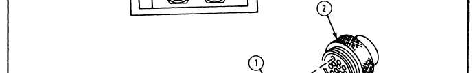
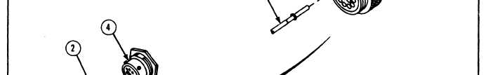
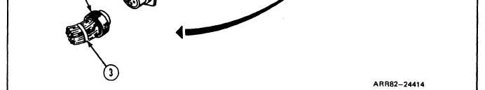
Using insert tool, install wires (1) in new connector (2).
2. Put on tiedown straps (3).
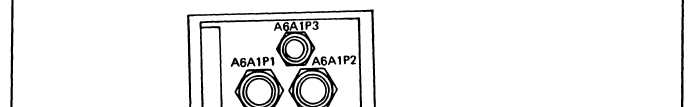
3. Plug connector (2) into PCU connector A6A1P2 (4).
Follow-on Maintenance:
1. Install power module A6; refer to task 22.
2. Install thermal system test controller; refer to para. 2-5, task 8.
3. Install thermal system test controller case cover; refer to volume 1, para. 4-18.
TASK 10 ENDS HERE
Volume IV
Para. 2-9, Task 10
2-243