T M 9 - 4 9 3 1 - 3 8 1 - 1 4 & P -2
FRAME 1
Remove Electrical Load Bank A5:
1.
2.
3.
4.
5.
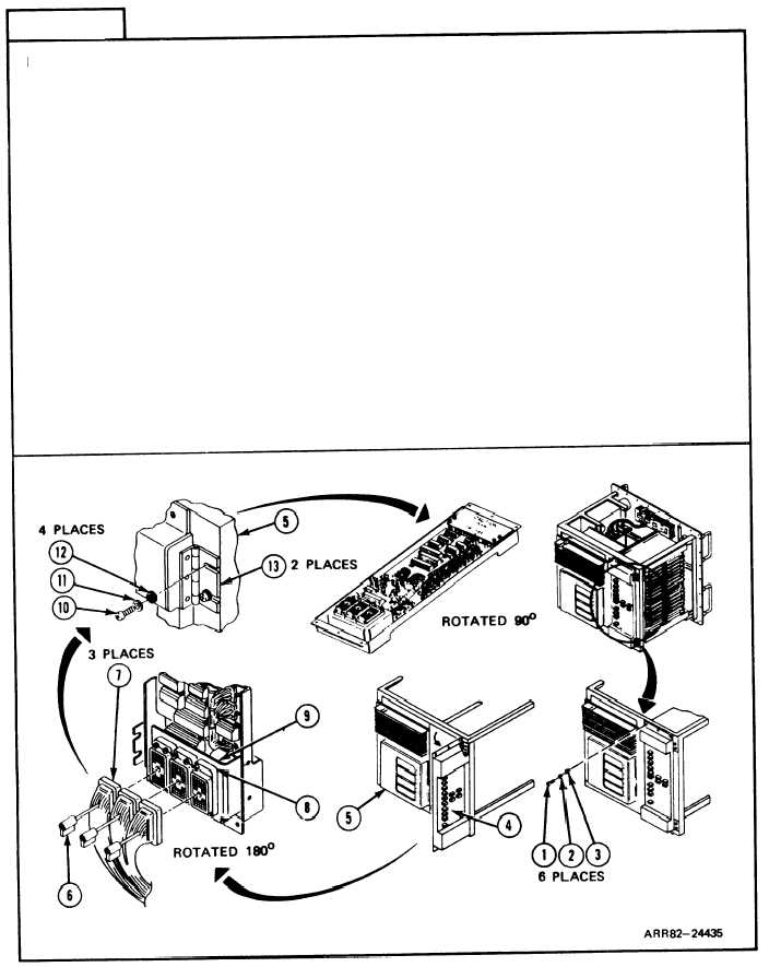
Unscrew and takeout six machine screws (1), lockwashers (2), and flat washers (3)
from electrical load bank (4) with screwdriver. Get rid of lockwashers (2).
Open load bank (4).
NOTE
If only access to load bank (4) is required, go to follow-on
maintenance, and TASK 1 ENDS HERE. If removing load
bank (4) from test controlIer chassis (5), go to step 3.
Turn handles (6) on three harness plugs (7) one quarter-turn counterclockwise and
take plugs (7) off of three receptacle connectors (8) on connector bracket (9).
Unscrew and take out four machine screws (10), Iockwashers (11), fIat washers (12)
from two butt hinges (13) with screwdriver. Get rid of lockwashers (11).
Take load bank (4) off of test controlIer chassis (5) and place on a clean work
surface.
Follow-on Maintenance:
NOTE: To instalI electrical load bank A5, refer to task 16.
TASK 1 ENDS HERE
Volume IV
Para. 2-11, Task 1
2-281

