
TM 5-4520-208-15
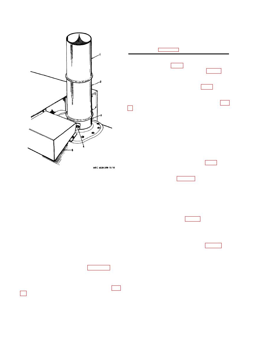
1
Exhaust pipe, with screen
Exhaust pipe, without semen
2
Exhaust stack
3
Engine exhaust pipe
4
Exhaust shield
5
Figure 10--Continued.
d. Place a 6-inch air hose on each of the
three duct holders (fig. 2).
cabinet.
f. Install cabinet and close air inlet door.
towing position, and tow to the new worksite.
Several heaters may be towed in tandem by
attaching their tow bars to the tow pin (fig.
Caution: Maximum permissible towing speed
is 20 mph over smooth paved surfaces and 10
mph over rough terrain.
15. Reinstallation After Movement to a
New Worksite
a. Uncouple all heaters if any were towed in
tandem.
vertical position.
c. Install the duct or ducts suitable for the
work to be performed (para 13).
Figure 10. Exhaust pipes, installed view.
Section Ill. CONTROLS AND INSTRUMENTS
b. The temperature gage is a dial-type instru-
16. General
ment which indicates the actual temperature of
This section describes, locates, illustrates, and
the discharge air in degrees Fahrenheit
furnishes the operator, crew, or organizational
maintenance personnel sufficient information
the discharge air outlet regulates the temper-
shout the various controls and instruments for
ature gage.
proper operation of the BT400-40 and BT400
401 portable heaters.
19. Fuel Control Valve Knob
17. Controls and Instruments
mounted in the control box. The fuel control
valve turns the combustor off by passing fuel
The purpose of the controls and instruments
flow to the nozzle. Open the contorl box cover
and the normal and maximum readings of the
to gain access to the control.
instruments are illustrated in figure 11.
b. When the knob is depressed, fuel flows
to the fuel nozzle. The fuel flow is stopped
18. Discharge Air Temperature Gage
when the knob is pulled upward. Length of
travel of the plunger attached to the knob is
approximately 1/8-inch.
18
