TM 5-4520-208-15
with no outlet for the air and possible damage
from a heat buildup within the heater.
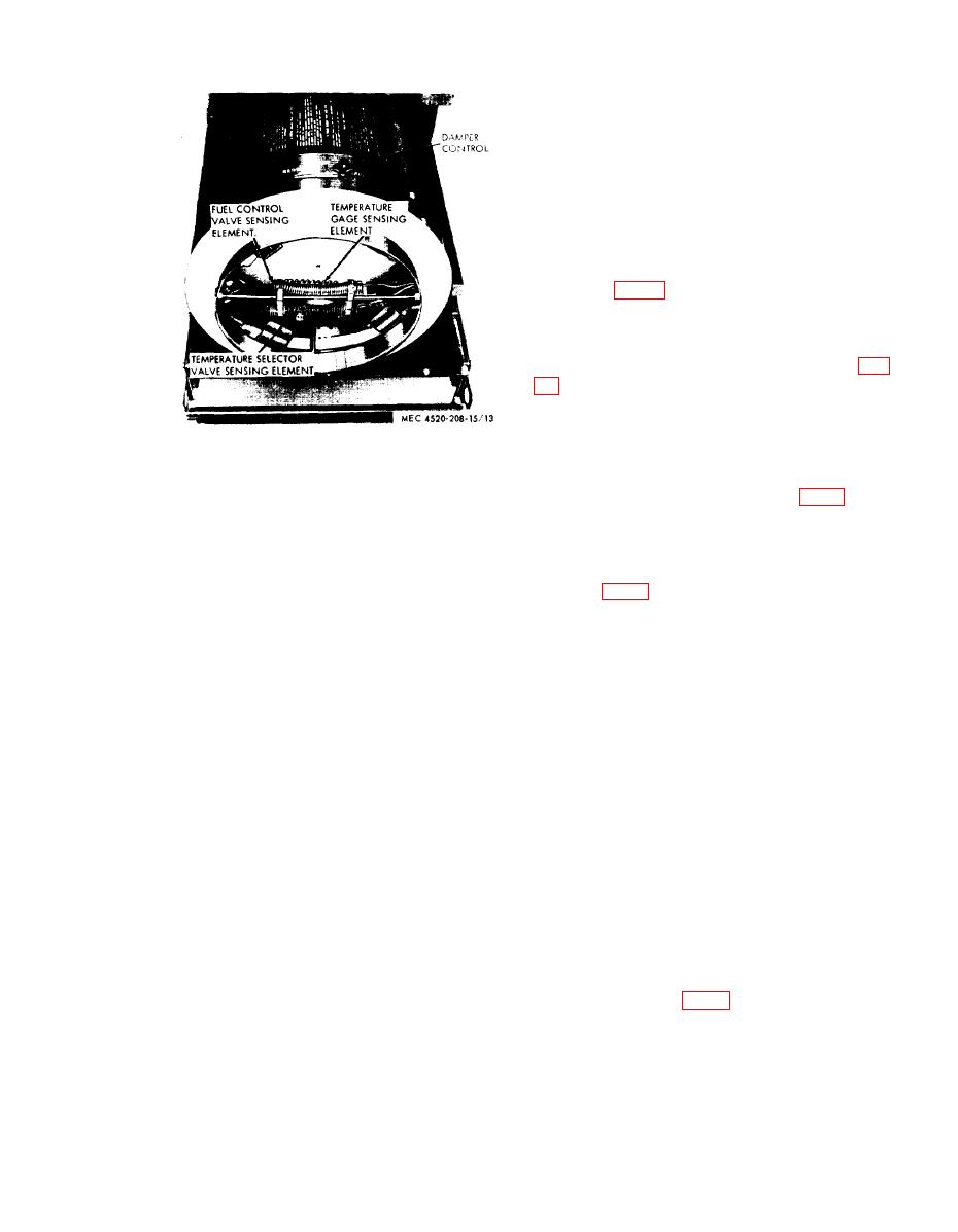
30. Sensing Elements
a. General. Three sensing elements are
mounted in front of the damper in the dis-
charge end of the heater. The elements are
directly in the air stream so the temperature of
the air directly affects the elements.
b. Discharge Air Temperature Gage Sensing
temperature to the temperature gage! mounted
in the control box. The temperature gage reg-
isters the temperature in degrees Fahrenheit.
c. Fuel Control Valve Sensing Element (fig.
in the fuel control valve. When the discharge
air temperature exceeds safe limits (about 350
F) the gas in the element will expand enough
to force the diaphragm up and open the fuel
Figure 13. Heater discharge air controls.
control valve. Opening the fuel control valve
opens the primary bypass line (fig. 3) and
heater. The control handwheel is mounted on
reduces the outlet pressure at the fuel pump.
the top of the casing.
The drop in pressure makes it impossible for
b. The damper control, attached to the damp-
the nozzle to receive fuel, stopping combustion.
er, is secured by the handwheel, To move the
d. Temperature Selector Valve Sensing
damper control, loosen the handwheel.
Element (fig. 13). Gas in the temperature se-
lector valve sensing element controls a dia-
c. Moving the damper control as far as pos-
phragm in the temperature selector valve. As
sible to the left (when facing discharge end)
the discharge air reaches the selected tempera-
completely closes the damper. As the damper
ture, the gas expands and, through action of
control is moved to the right the damper opens
the diaphragm, opens the temperature selector
increasing the volume of discharge air leaving
valve, decreasing the nozzle fuel flow. The
the heater. The damper controls the volume
action of the temperature selector valve will
from fuel to one-half the rated flow. The dis-
maintain the selected temperature by increasing
charge air outlet cannot be completely closed,
or decreasing fuel flow through the nozzle.
preventing accidental operation of the heater
Section IV. OPERATION OF EQUIPMENT
represents a different problem, the operator
31. General
may have to vary given procedures to fit the
a. The instructions in this section are pub-
individual job.
lished for the information of the personnel
responsible for operation of the BT400-40 and
32. Starting
BT400-40-1 heaters.
a. Preparation for Starting.
b. The operator must know how to perform
every operation of which the heater is capable.
(1) On Model BT400-40 heaters, remove
cabinet (fig. 1) by disengaging
This section gives instructions on starting and
latches.
stopping the heater. Since' nearly every job
21


