
TM 5-4520-208-15
b. Turning the temperature selector valve
indicate E (empty), 1/4, 1/2, 3/4, and F
knob clockwise increases the discharge air tem-
(full).
perature; turning it counterclockwise decreases
27. Time Totalizing Meter (BT400-40)
the temperature.
mounted above the magneto. A rubber belt
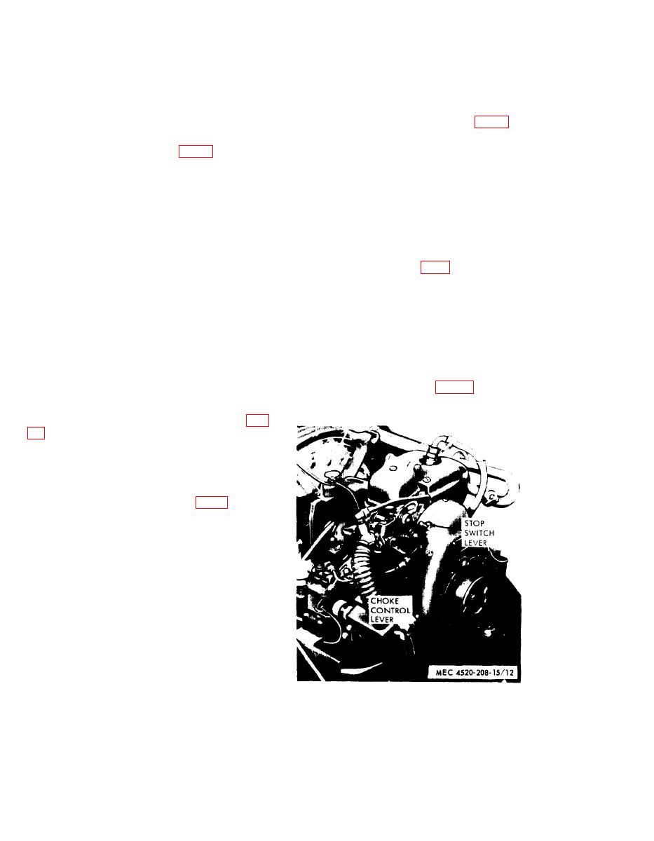
22. Choke Control
(preformed packing) drives a pulley attached
to the time totalizing meter shaft. The belt is
cated on the carburetor. It enables the operator
driven by the magneto pulley.
to enrich the fuel mixture for cold weather
b. The time totalizing meter is direct read-
starting.
ing and records the heater operating time in
b. The control is an external lever which
hours.
can be held in any desired position. When the
lever is rotated fully counterclockwise the valve
28. Electric Motor Power Unit On-Off
is closed and the gas mixture is enriched.
Switch
23. Stop Switch Lever
eration of the electric motor power unit. The
a. The stop switch lever (fig, 12) is mounted
ON-OFF switch is mounted on the electric
on the top of the flywheel housing.
motor power unit junction box.
b. To stop the engine power unit, set switch
b. The ON-OFF switch is a two-position, tog-
lever to OFF position.
gle type switch and is used to start and stop
the motor.
24. Starting Rope
a. The starting rope is furnished for the pur-
29. Damper Control
pose of manually cranking the engine power
unit.
a rotating damper at the discharge end of the
b. Engage the rope in the flywheel flange
and pull rope to start the power unit (fig.
25. Fuel and Exhaust Controls
a. The engine hose assembly leading from
the fuel tank is a flexible hose' equipped with
a quick-disconnect coupling (fig. 7). Push
coupling away from fuel filter to disconnect
hose assembly.
b. An exhaust extension leading from the
manifold has a flange near the end. The ex-
haust extension is inserted into the exhaust
pipe and the flange bears on a mating flange
on the exhaust pipe under spring pressure to
provide a gastight fitting.
26. Fuel Gage
a. The fuel gage is mounted beneath the
heat exchanger on the right side of the base.
The fuel tank cap is next to the gage.
b. The fuel gage is a needle-indicating type,
direct reading gage. Graduations on the gage
Figure 12. Gasoline engine power unit controls.
20
