
TM 5-4520-208-15
(3) Remove four screws (6), lockwashers
combustor with 16-self-locking nuts
(9) and flat washers (8).
(7), and nuts (8) securing four air
control baffles (10) to the air control
(2) Install combustor plate (5) as de-
(13) and remove air control baffles.
scribed in paragraph 83.
(3) Install nozzle holder (par. 87, BT-
(4) Remove three screws (1), lockwashers
400-40 or para 92, BT400-40-1).
(11), and nuts (12) securing air con-
(4) Install power unit (para 12).
trol to casing (9) and remove air
control.
151. Air Control Components
(5) Remove two nuts (10, fig. 49) and
lockwashers (11) and remove bulb
a. Removal.
support (13) from duet adapter as-
(1) Remove duct adapter assembly and
sembly.
sensing units (paras 99 and 100)
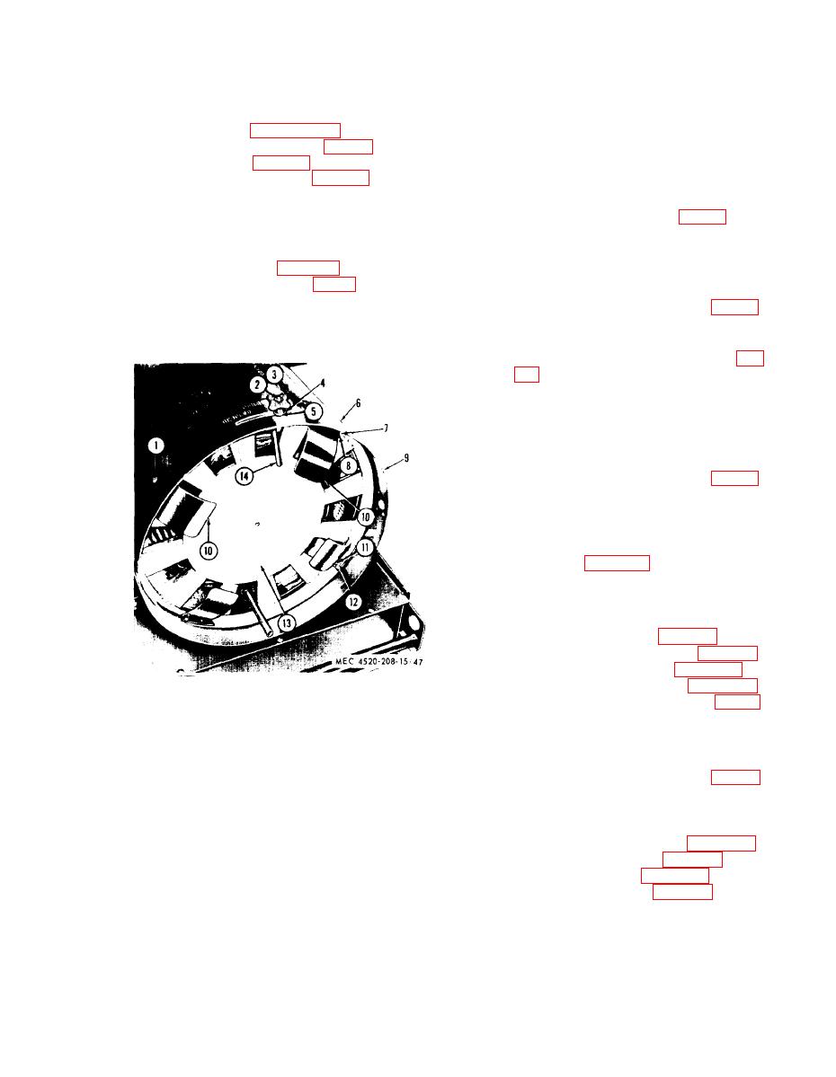
(2) Remove cotter pin (2, fig. 47), hand-
b. Installation.
wheel (3), flat washer (4), and rub-
(1) Position the air control (13, fig. 47)
ber washer (5) and remove damper
in casing (9) and install three screws
control (14).
(l), lockwashers (11), and nuts (12).
(2) Position the four air baffles (7, fig.
four screws (6), lockwashers (8),
and nuts (9).
(3) Install bulb support (13) on duct
adapter (12) and secure with four
nuts (10) and two lockwashers (11).
(4) Install damper control (14, fig. 48)
and secure with rubber washer (5),
flat washer (4), handwheel (3), and
cotter pin (2).
(5) Install sensing units and duct adapter
assembly (paras 99 and 100).
152. Heat Exchanger
a. Removal.
(1) Removal power unit (para 12).
(2) Remove the exhaust stack (para 80).
(3) Remove the combustor (para 150).
(4) Remove the air control (para 151).
Screw, machine, No. 10-24 x 3/8 in (3)
1
(5) Slide the heat exchanger (17, fig. 48)
2
Pin, cotter, 1/16 x 1/2 in.
from the casing.
3
Handwheel
(6) Remove gasket (18).
4
Washer, flat, 1/4 in.
5
Washer, rubber
b. Installation.
6
Screw, machine, No. 10-24 x 3/8 in. (4)
7
Washer, lock, No. 10 (4)
(1) Slide heat exchanger (17, fig. 48)
8
Nut, plain, hex, No. 10-24 (4)
into casing and position to line up
9
Casing
exhaust stack holes in heat exchanger
10
Air control baffle (4)
with holes in casing and gasket (18).
11
Washer, lock, No. 10 (3)
(2) Install the air control (para 151).
12
Nut plain, hex, No. 10-24 (3)
13
Air control
(3) Install exhaust stack (para 80).
Damper control
14
(4) Install combustor (para 160).
(5) Install power unit (para 12).
Figure 47. Air control, removal points.
91
