
TM 5-4520-208-15
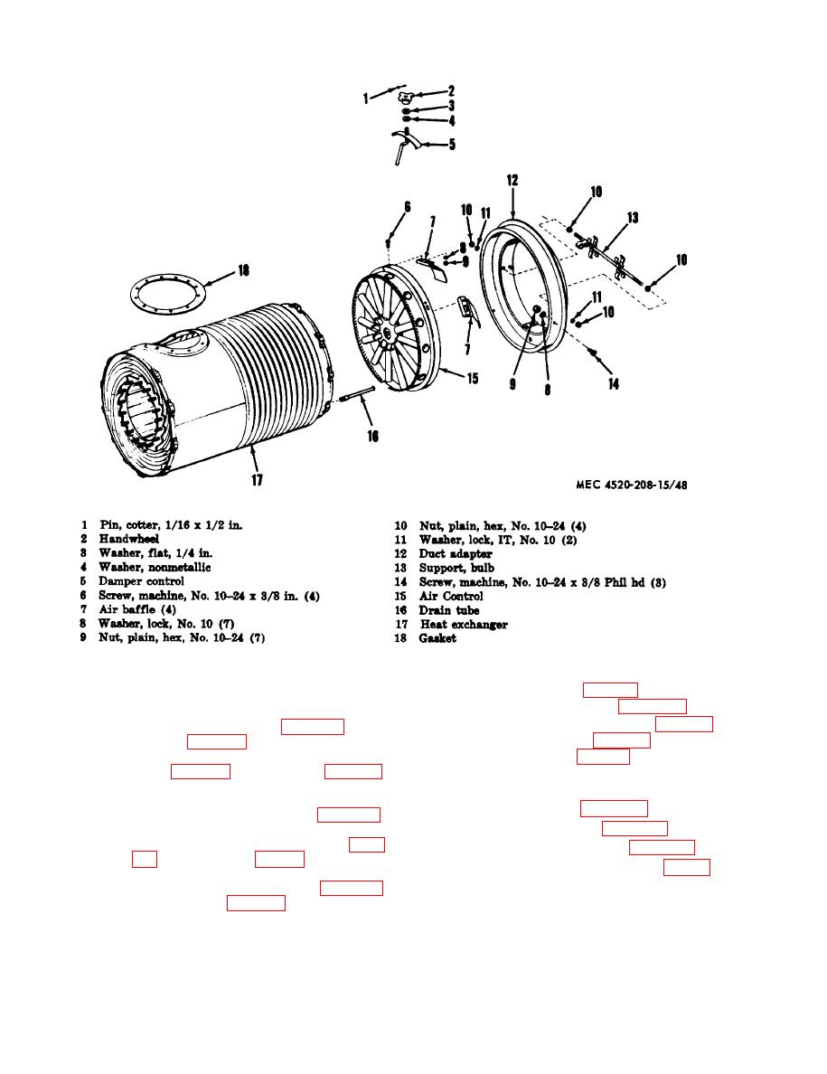
Figure 48. Heater exchanger and air control, exploded view.
(6) Remove fuel tank (para 95) and heat-
153. Casing, Bulkheads, and Base
er controls and block (para 100).
a. Removal.
(7) Remove engine exhaust pipe (para 79)
(1) Remove power unit (para 12), and
and exhaust stack (para 80).
cabinet (para 70).
(2) Remove fuel pump and tube assem-
(8) Remove magneto (pars 82) and igni-
tion cable (prow 83).
BT400-40-1).
(9) On Model BT400-40, remove time
(3) Remove power unit hose assembly
totalizing meter (para 102).
(para 86, BT400-40 or para 91,
(10) Remove air control (para 151).
BT400-40-1).
(4) Remove fuel atomizing nozzle (para
(11) Remove heat exchanger (para 152).
(12) Remove sixteen screws (43, fig. 49)
1).
and lockwashers (42) and remove left
(5) Remove heater fuel filter (para 88,
and right side panels (41 and 50)
BT400-40 or pars 93, BT400-40-1).
92
