TM 5-4520-208-15
tached, in bore of plate. Secure nozzle
plug electrode (3).
holder by engaging clamp (3) in
notches on combustor.
(2) Install the plate (4, fig. 31) on com-
(5) Insert ignition cable (7) through hole
bustor (2).
in casing, and secure grommet (6)
(3) On Model BT400-40 heaters, insert
around cable. Connect ignition cable
nozzle holder (1) in bore of plate,
to igniter plug (5) and magneto (9).
tighten tube assembly fittings, and in-
(6) Refer to paragraph 77 and install the
stall clamp (3) in notches on cornbus-
mounting ring.
tor to secure nozzle.
(4) On Model BT400-40-1 heaters, insert
(7) Refer to paragraph 12 and install the
nozzle holder (1), with clamp at-
power unit.
Section XII. HEATER FUEL SYSTEM (BT400-40)
84. General
The heater fuel system consists or a fuel
tank mounted in the base, fuel filter, tube as-
semblies, fuel pump, fuel control box, and
combustor.
85. Fuel Pump and Heater Fuel Tube
Assemblies
a. General The fuel pump is mounted on a
bracket to the left of the nozzle. The pump is
belt-driven by the power unit. A flexible hose
assembly delivers fuel, through the fuel filter,
to the fuel pump. During the heating cycle
fuel travels from the nozzle and secondary
bypass line. Bypass fuel is returned to the fuel
tank from the nozzle and secondary bypass
line.
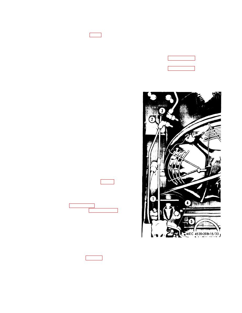
b. Pressure Test and Adjustment.
(1) Disconnect fuel pump-b-nozzle pres-
sure tube assembly (2, fig. 33) from
elbow (3).
(2) Using an adapter, connect a pressure
gage with a maximum reading 200
psi in pressure tube assembly (2).
(3) Refer to paragraph 12 and install pow-
er unit. Refer to paragraph 32 and
start the heater and observe pressure
gage reading. The pump should be
operating at 150 psi, plus or minus 2
psi.
(4) If the reading is not within operating
pressure tolerance, remove nut (1) and
1
Nut
turn ajusting screw clockwise to in-
2
Pressure tube assembly
crease the pressure, or counterclock-
Elbow
3
wise to decrease pressure.
4
Bypass tube assembly
5
Fuel pump
(5) Stop the heater (para 33). Remove the
pressure gage and connect the pres-
Figure 33. Fuel pump, pressure test points
sure tube assembly (2).
(BT400-40).
53


