TM 5-4520-253-13
REPAIR PC BOARD ASSEMBLY HARNESS RECEPTACLE AND PLUG (CONT)
e.
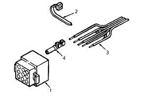
Refer to table 4-2.1 and push female terminals (4) into numbered sockets in
receptacle (1) .
Wire colors and socket numbers must be in accordance with
t h e t a b l e .
Table4-2.1 Harness Receptacle Wlrlng Sequence
Wlre Color
Socket No.
Blue
1
White
2
Red
3
Violet
4
Yellow
5
Red/White
6
Orange
7
Green
8
Brown
9
f. Install cable ties (2) to replace any removed.
2. Repair plug as follows:
a. Pull plug (6) out of side of heater case.
b. Cut off and discard cable ties (7) as needed to allow access to harness wires (8).
c. Tag wires (8) and cut as close to plug (6) as possible. Discard plug.
d. Strip 1/4 inch (6.35 mm) of insulation from end of each wire (8). Crimp male terminal (9) on each wire.
4-26.2
Change 2

