R E M O V E / I N S T A LL
TM 5-4520-253-13
C O M B U S T I O N B L O W E R A N D H O U S I N G ( C O N T)
2.
3.
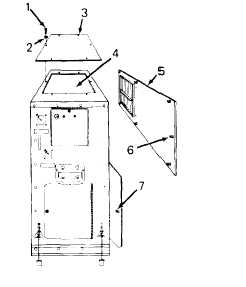
Reach through heater case opening (4) and disconnect louver linkage from louvers of left-hand
louver panel (5).
Remove left-hand louver panel (5) by unlocking eight studs (6). Open left heater case door by
unlocking stud (7).
4.
5.
6.
7.
8.
9.
10.
Remove screw (8) and lock washer (9). Lift out support tube (10).
Loosen hose clamp (11) and pull off blower air duct (12).
Disconnect yellow wire (13) and white wire (14) from yellow and white wires of printed circuit
(PC) board assembly.
Remove four screws with lock washers (15) and lift out combustion blower and housing assem-
bly (16).
Remove four screws (17) and lock washers (18) and PullI blower housing cover (19) away from
blower housing (20). Unsolder wires (21 and 22) from terminals of capacitors (23).
Remove four screws (24) and lock washers (25). Pull blower motor
out of blower housing (20).
Remove four screws (28) and lock washers (29) and separate blower
support (27).
(26) and blower support
motor (26) from blower
(27)
4-41