TM 9-2540-205-24&P
BLOWER ASSEMBLY - HUPP MF510B, MF510C, MF60A-24V, MF60B-24V - Continued
LOCATION
ITEM
ACTION
REMARKS
INSTALLATION - Continued
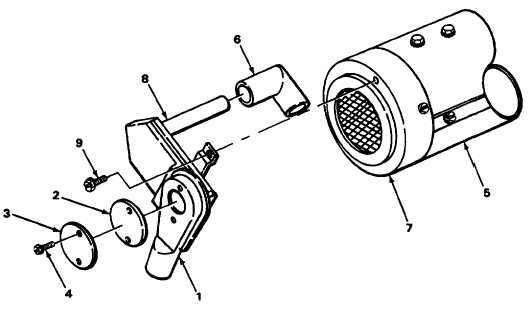
53. Housing (1)
54. Cover (3)
55. Heater (5)
Gasket (2) and cover (3)
Install.
Two screw assemblies (4)
Screw in and tighten.
NOTE
Step 55 through 57 apply to MF510B, MF510C, and MF60B-24V.
Elbow (6)
a. Apply sealant.
b. Install.
56. Elbow (6) and inlet cover (7)
Duct assembly (8)
a. Apply sealant.
b. Install.
57. Duct assembly (8) and inlet
Two screw assemblies (9)
Screw in and tighten.
cover (7)
NOTE
FOLLOW-ON MAINTENANCE:
1. Install overheat switch (page 3-57).
2. Install control bracket assembly (page 3-37).
TASK ENDS HERE
3-71

