TM 9-4520-251-14
5-13 VALVES AND TAPPETS (CONT)
Location/Item
Action
Remarks
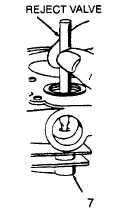
4. Valve guide
If flat end of reject gauge (Briggs & Stratton Tool
No. 19122) can be inserted 5/16 inch (7.94 mm)
into valve guide (7), valve guide is worn. Forward
engine to general support maintenance for repair
or replacement.
NOTE
Apply antiseize compound (Appendix E, Item 1) on valve stems
and guides before installing. Be sure no compound is on
ends of valve stems or tappets.
5. Exhaust valve
If valve guide does not need repair or replacement,
installation
place spring (9), rotocap (11), and retainer (12)
in compressor and compress until spring is solid.
Insert compressed spring, rotocap, and retainer into
valve chamber (8) and drop exhaust valve (1) into
place, pushing stem through rotocap and retainer.
Using needle nose pliers, insert pin (10) in stem of
exhaust valve and lower notch in retainer onto pin.
Remove compressor.
lNSPECTION/REPLACEMENT
NOTE
For inspection of tappets, it is assumed that crankshaft and cam gear have
been removed as described in paragraph 5–12. After inspection reas-
semble crankshaft and cam gear. Install new crankcase gasket when re-
placing crankcase cover.
6. Tappets
Inspect tappets (13) for cracks, bent stems, and signs
of wear or other damage. If defective, replace.
CAUTION
Piston must beat top dead center at end of compression stroke to en-
sure that both valves are closed.
NOTE
Check clearance when engine is cold.
7.
Exhaust and
Turn crankshaft to top dead center at end of com-
intake valve
pression stroke. Both valves are not closed. With feeler
clearance
gauge, check clearance at exhaust valve (1) and intake
valve (3). Clearance at exhaust valve must be 0.009 to
0.011 inch (0.229 to 0.279 mm). Clearance at intake
valve must be 0.005 to 0.007 inch (0.127 to 0.178 mm).
If these specifications are not met, adjust tappet clearance.
5-31


