TM 9-4520-251-14
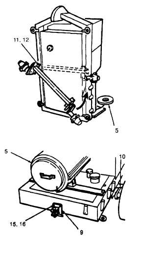
h. Mount one end of axle (10) using cap screw (11)
and washer (12). Swing axle to horizontal posi-
tion and install remaining cap screws and wash-
ers.
i.
Install brakes using cap screws (13) and wash-
ers (14). Handle must be positioned on side of
heater shown in illustration.
j.
Mount and adjust wheels (7) as described in
paragraph 4–67.
k.
Remove clevis pin (9 B), hitch pin (9C) and install
tow bar (9A) in “a downward position.
l.
Lower heater and install backtow
screws (15) and washers (16).
(9) using
4-4 RECIEVING INSPECTION.
Perform receiving inspection of heater in the following manner:
a.
Inspect the equipment for damage incurred during shipment, If the equipment has been damaged,
report damage on DD Form 6, Packaging Improvement Report.
b.
Check the equipment against the packing slip to see if the shipment is complete. Report all discre-
pancies in accordance with the instructions of DA PAM 738–750.
c. Check to see whether the equipment has been modified.
4-5
INSTALLATION SITE PREPARATION.
The heater is designed so that it is adaptable to a variety of installation arrangements. Most installations are
made by preparing an opening in an exterior wall of the room or enclosure to be heated, Alternate installations
may be made with the heater with different air duct hose configurations. The following are minimum require-
ments for all installations.
a.
A relatively level surface capable of bearing the weight of the heater. To ensure proper fuel and oil
levels the surface should be level with 5 degrees from front to back and side to side.
b. An unobstructed flow of air from outside the heated area to the noise baffle and exhaust stack.
c.
Access to the front and back of the unit for routine operation and servicing and for necessary mainte-
nance actions.
4-3