
TM 9-4520-271-14
0038 00
ASSEMBLY - Continued
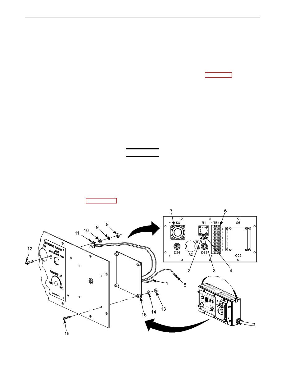
Remote Controller S6 and Temperature Sensor TP-1 Installation
1.
Position remote controller S6 (16) and secure with four screws (15), washers (14), and nuts (13).
2.
Install screw (12), temperature sensor TP-1 (11), two washers (10), lockwashers (9) (item 26, WP 0062 00), and nuts (8).
3.
Connect white wire S6-P12 (5) to mode switch S8 (7) terminal 14. Remove wire marker tag.
4.
Connect following seven wires (5) to terminal board TB4 (6). Remove wire marker tags.
Red wire S6-P1 to TB4-1
White wire S6-P13 to TB4-2
Blue wire S6-P2 to TB4-4
Orange wire S6-P14 to TB4-5
Red wire S6-P9 to TB4-6
Black wire S6-P11 to TB4-7
Yellow wire S6-P10 to TB4-8
WARNING
Avoid breathing fumes generated by soldering. Eye protection is required. Good general ventilation is
normally adequate.
5.
Solder three wires (1) to thermostat control R1 terminals (2, 3, and 4). Remove wire marker tags.
6.
Install wire ties as required.
7.
Install front panel assembly (WP 0038 00-21).
0038 00-17
