T M 9 - 4 9 3 1 - 3 8 1 - 1 4 & P - 2
FRAME 22
InstalI Load Bank:
NOTE
If load bank A5 (1) was removed and taken off of chassis (2),
do steps 1 through 4. If load bank was opened for access
only, go to step 4.
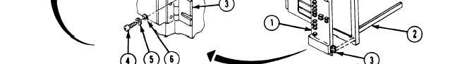
1.
Position electrical load bank (1) on chassis (2) and line up butt hinges (3) with holes
in chassis (2).
2. Screw in and tighten four machine screws (4), new lockwashers (5), and flat washers
(6) into hinges (3) with screwdriver.
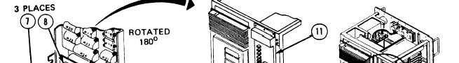
3. Line up three electrical connector plugs (7) with receptacle connector bodies (8) on
connector bracket (9). Turn handles (10) on three plugs (7) one quarter turn
clockwise to lock plugs (7) to connectors (8).
4. Close load bank (11) and put in six machine screws (12), new Iockwashers (13), and
flat washers (14) with screwdriver.
Follow-on Maintenance:
1. Install thermal system test controlIer; refer to para. 2-5, task 8.
2. install thermal system test controller case cover; refer to volume 1, para. 4-18.
END OF ELECTRICAL LOAD BANK A5 MAINTENANCE
Volume IV
Para. 2-11, Task 16
2-317