T M 9 - 4 9 3 1 - 3 8 1 - 1 4 & P - 2
FRAME 20
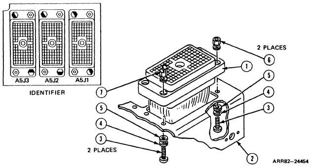
Install Connector:
1.
Line up
NOTE
Use this task to install any of three connectors A5J1, A5J2,
or A5J3. Connector A5J3 (1) is shown.
holes in receptacle connector body (1) with holes in connector bracket (2).
CAUTION
If keys are put back and turned wrong way on connector, the
wrong plug maybe installed on the connector and equipment
can be damaged. Be sure to put keys back in as shown in
identifier.
2. Screw in four machine screws (3), four new lockwashers (4), four flat washers (5),
two hexagon plain nuts (6), and two electrical polarizing keys (7) with screwdriver.
3. Using torque screwdriver and bit, torque screws (3) between 5 and 6 pound-inches
(0.57 to 0.68 Newton meter).
Follow-on Maintenance:
1. InstalI panel connector bracket; refer to task 15.
2. Install electrical load bank A5; refer to task 16.
3. install thermal system test controller case; refer to para. 2-5, task 8.
4. install thermal test controller case cover; refer to volume 1, para. 4-18.
TASK 14 ENDS HERE
Volume IV
Para. 2-11, Task 14
2-313