TM 9-4520-251-14
6-5
CRANKCASE COVER AND CYLINDER ASSEMBLY (CONT)
Location/Item
Action
Remarks
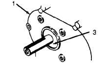
2. Oil seal in
Remove and discard defective oil
crankcase cover
seal (3). Lubricate inside diameter
of seal with Lubriplate (Appendix E,
Item 3) or equivalent before
assembly. Position sharp edge of
oil seal toward inside of engine and
press in as far as it will go. Installed
oil seal should be recessed 3/16 inch
(4.69 mm).
3.
Primary
Bore measure–
ment and
resizing
NOTE
repair of cylinder assembly consists of honing cylinder.
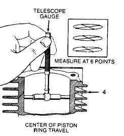
Using a telescope gauge (Appendix B,
Section Ill, Item 16)
and dial caliper (Appendix B,
Section III, Item 17), de_
termine size of bore in cylin-
der assembly (4). Take right
angle measurement at six
points as illustrated. If bore
in cylinder assembly is more
than 0.005 inch (0.13 mm)
oversize or 0.0025 inch
(0.06 mm) out of round, it
must be replaced. Standard
size is 2.5615 to 2.5625
inches (65.062 to 65.088 mm).
NOTE
Do not deglaze wall in bore of cylinder assembly if only installing piston
rings.
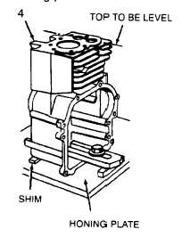
4. Honing setup
Clean bore in cylinder assembly (4)
at top and bottom to remove burrs
and pieces of head gasket. Fasten
cylinder assembly to heavy iron
bracket or use honing plate. Be
sure top of cylinder assembly is
level. Use shim if necessary.
Use level to align drill press
spindle with bore in cylinder as-
sembly. Lubricate surface of drill
press table liberally with oil (Appendix E,
Item 8). Set honing plate
and cylinder assembly on drill
press table. Do not anchor to
drill press table. Place hone
6-11