T M 9 - 4 9 3 1 - 3 8 1 - 1 4 & P - 2
FRAME 31
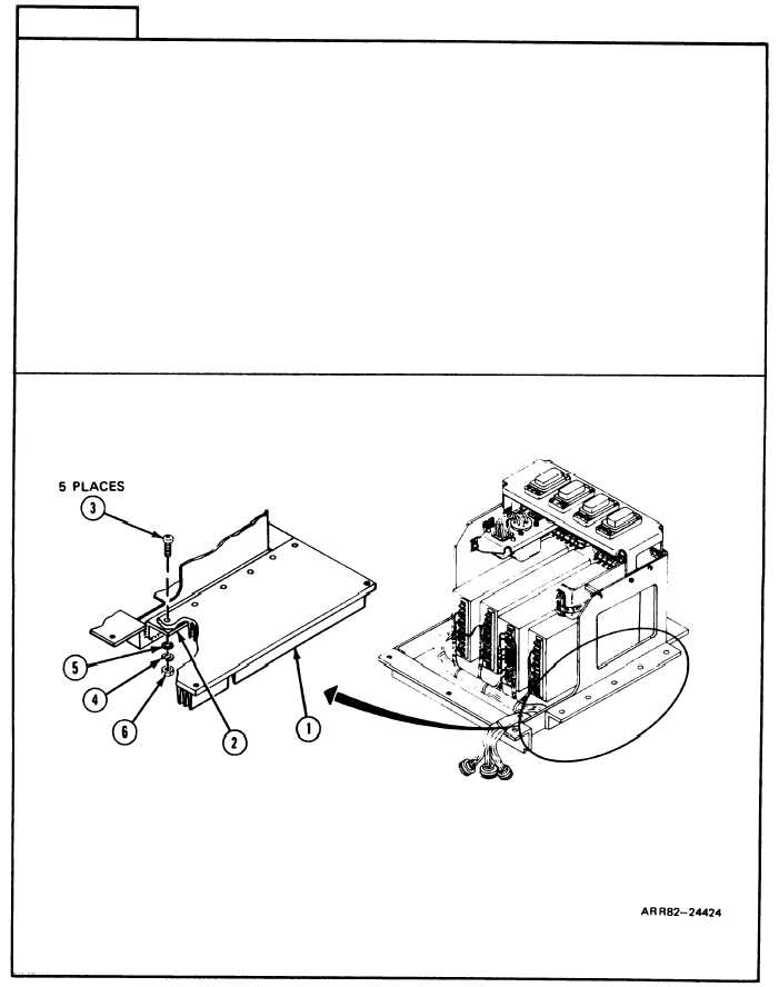
Install Power Module Base:
1.
Position power module base (1) on enclosure angle (2).
2. Screw in five machine screws (3), new Iockwashers (4), flat washers (5), and hexagon
plain nuts (6) with screwdriver and wrench.
3. Using torque screwdriver and socket, torque nuts (6) between 12 and 15 pound-inches
(1.4 and 1.7 Newton meters).
Follow-on Maintenance:
1. Install power controI unit A6A1; refer to para. 2-10, task 2.
2. Install power module A6; refer to task 22.
3. Install thermal system test controller; refer to para. 2-5, task 8.
4. Install thermal system test controller case cover; refer to volume 1, para. 4-18.
TASK 16 ENDS HERE
Volume IV
2-260
Para. 2-9, Task 16