T M 9 - 4 9 3 1 - 3 8 1 - 1 4 & P -2
FRAME 37
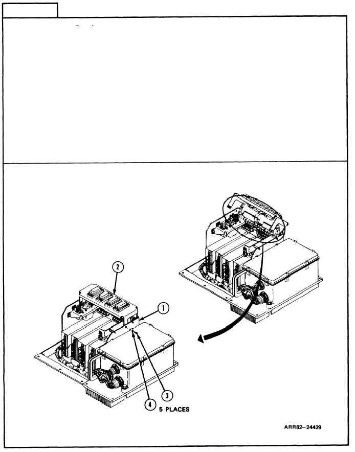
Install Connector Bracket:
1.
Line up holes of enclosure (1) with holes in connector bracket (2).
2. Screw in five machine screws (3) and fIat washers (4) in connector bracket (2) with
screwdriver.
3. Using torque screwdriver and cross tip bit, torque screws (3) between 9 and 12
pound-inches (1.02 and 1.36 Newton meters).
Follow-on Maintenance:
1. Install power module A6; refer to task 22.
2. Install thermal system test controller; refer to para. 2-5, task 8.
3. Install thermal system controller case cover; refer to volume 1, para. 4-18.
TASK 21 ENDS HERE
Volume IV
Para. 2-9, Task 21
2-271